G 8 G M U   


Having heard a superb talk at the Coventry Amateur Radio Society by John Heath G7HIA about satellite working & the work of AMSAT... (it motivated me) I decided to have a play. Having looked at the prices of a suitable antenna & the implications for others just joining the hobby I produced a simple antenna design that required no special tools or knowledge beyond that a radio amateur should have, even a foundation licensee. The 'GMU / B&Q' antenna was born. Visit said DIY establishment walk out with antenna in 'kit form'. 1 piece of wood & 2 pieces of 10mm aluminum angle, screws & washers.
Click for larger images Click for larger images Click for larger images
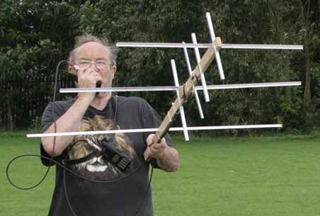
This antenna really does work well, having now made many contacts through orbiting satellite A051. The tests being carried out in the full view of my neighbours who are about ready to certify me for the strange behaviour.

CONSTRUCTION
Let us build the 435Mhz (70cm) antenna so we can listen to the downlink.
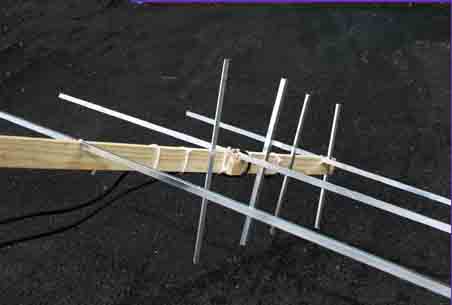
This is simple, tools required, accurate rule or tape measure, hacksaw, file drill, 3.5mm drill bit & set square if you must I didn't.
Materials 10mm Aluminum angle. length of wood pack of screws & washers. This takes you as far as the connection to the co-axial feeder.
First making the 435 MHz antenna using the dimensions set out here.

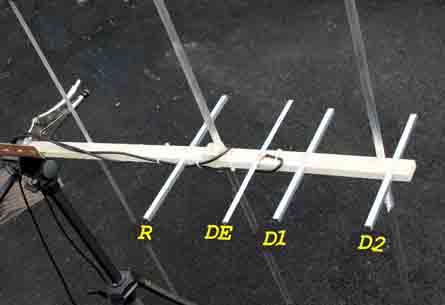
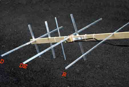
On the broad face of the wood measure in from one end 25mm & mark this will hold D2. measure 400mm & mark, this will hold the reflector R. This gives you the boom length of the 435 MHz antenna & the post ions from the second director D2 & reflector R respectively, do not cut anything yet. Measure & mark for the driven element DE 155mm from the reflector, now from the driven element to the first director D1 measure 150mm & mark. your boom should now be marked out for the four elements (we count the driven element in its 2 parts as one element). Make sure the markings are square to the boom. 
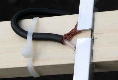
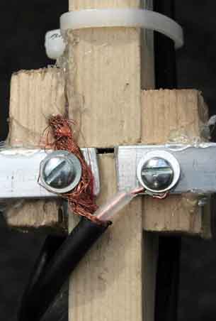
Very carefully cut a slot at each mark so the right angle aluminum slots in all the way down but is held tightly, very careful flexing of the timber will assist this as you offer one face of the angle into the saw cut. Check each saw cut in turn, that it will take one face of the angle.
It is now time to cut the aluminum to form the elements. NOTE aluminum & other metals once cut can cut! Beware sharp edges file to remove burrs.
D2 measure 271mm cut, file & the write on the element D2.   D1 measure 288mm cut, file & the write on the element D1 the driven element made up of 2 pieces of angle each 163mm measure cut & file,.again mark each DE. Last but not least the reflector at 345mm again cut file & mark. Do not discard the angle that is left over you will need this later.

Slot each element into its carefully sawn slot the angle should face to longest end of the boom (backwards) for all except he driven element the driven element should have a gap a the the centre of 8mm.Click for lager image Fit length of co-axial cable which is good at UHF many cables are very poor at these frequencies. For now simply make a push fit joint from the centre of the element & the coax inner & outer, inner to the left hand element looking from the operators standpoint when holding the antenna. Secure with a couple of cable ties fit the appropriate connector to fit your rig usually BNC. Take a listen at your 70cm local beacon or repeater to check it receives ok. As the 432Mhz section of the antenna intended to be receive only you may stop at this stage. I went further with analizing equipment & trimmed the antenna to the sizes published, you may transmit low power QRP with an SWR bridge & tweak if you wish. Assuming it works lets take a break from construction & listen to a satellite.
AO51 is a good one to go for,it is mainly narrow band FM on the up link check the Amsat site as to it's daily schedule; AO51 is usually very busy. Follow this link to the AMSAT prediction page, you will need to enter AO51 & your location.

If you tried it I hope you were successful & heard something, when the antenna construction information is ended I shall go further into operating through AO51.
Back at the construction site you may fine it easier to remove the elements from the boom to make handling easier.
For the 145 MHz antenna use the narrow edge of the timber. Surpassingly there are only 2 elements to cut, the reflector & driven element, the director is the piece over from the the first part of the job.

Click for larger image
The Reflector is 1038 mm each of the 2 halves of the driven element is 470mm measure cut & file as for your earlier part of the project. For better or for worse or by mistake I had a 735mm offcut to make the director from.
Having done the metalwork make the following measurements on the boom. From the D2 slot on the 435Mhz antenna measure 675mm & mark, this is for the slot for the 145mhz reflector. Measure 329mm & mark for the driven element, the final measurement is for the only director on this part of the beam, it is 317mm forward of the driven element. For clarity the designations on the photographs yellow is the 435Mhz section & red for the 145Mhz.
Back at the woodwork as previously carefully cut slots for each element to fit. Center each element on the boom drill & screw to secure. I must admit a cheat if you look closely I have fitted 2 support blocks to increase the strength of support for the driven element, the driven element gap is 4mm.
As this antenna is used for transmitting the up link after fitting the coax make the usual safety checks then ensure that you are happy with the SWR readings. I have optimised the beam to work in the high end (satellite portion) of the UK 2 metre band.
Connecting copper cable to aluminum components is a recipe for corrosion setting in should the junction become damp. If you are to use this in such conditions at a greater cost fit brass driven elements with solder joints & lots of water proofing to stop moisture entering the co-ax cables.

My RX & TX Setup & Advice

On the receive side I use a very old Kenpro KT 44. It is still good for simplex & repeater work but not up to the standards of a modern rig. The main downfall is the tuning. When tracking a satellite the RX needs to be re tuned to take into account Doppler shift. We are all familiar with Doppler shift as the police car races towards us the pitch of the siren increases and as it goes away the pitch reduces. The same thing happens with satellite communications I find an overall shift of at least 20 kHz, trying to tune this on the KT 44 is hard work, go for a rig with either continuos (stepless) tuning or one that will tune in 5khz steps. I also use a pre amp giving at least 12db gain to help recover signals at the beginning at end of some of the passes, this is not necessary. The signal from the 7 watt transmitter on AO51 is often 'very loud'.

It is best to have separate TX & RX facilities so you can hear your signal through the satellite so you know you are in.

The TX side is a Yaseu VX 150 currently borrowed from M3HBM. The output is 5watts which when taking the gain of the beam (at least 3dbd) is more than adequate. To access AO51 it currently requires a CTSS tone of 67Hz; there is no need to correct for Doppler on the up link.

I have upgraded the radios to a Yaseu VX-170E for the up link & a Yaseu VX-77 for the downlink. The 2 radios worn on a belt across the shoulder aids operating.
Before you give forth with your callsign attempting a contact, take a step back & listen for a few passes it pays dividends in learning operating procedure. In the main contacts are short giving the IARU locator & signal reports. When using the predictions tables treat them as just that, I have known great variations between 2 sets of tables in respect of all the parameters. The advice is to listen before time and if nothing heard keep listening & tracking the beam either side of the predicted heading. It isn't difficult.

Working from an urban area, actually on the pavement by the QTH I heard over 12 countries in a very few days, and worked into France, Germany, Denmark, Norway, Russia, Portugal a yes and someone a few miles away in Staffordshire. I am having fun with it, there is just something about hearing your signal coming back from space, it's nothing like using a land based repeater.
Logging
Keeping a log is an issue in particular working portable. By the time you aim the antenna, hold the Mic. & track the RX tuning theres not much left to write with. I suggest you record your contacts on an MP3 device or good old tape & transfer to the permanent log later.


  Antenna in use at Caludon Castle Coventry,
as part of a Coventry Amateur Radio Society portable event as GX2ASF/P GX2ASF/P (Coventry Amateur Radio Society Club callsign) from Caludon Castle

So far so good
This page is under construction, you have your start up information I now suggest you look at the AMSAT site using the earlier link given. I hope this so far has been useful. I hope to come back to this page from time to time to update it.
There has been little to add in the 3 years this antenna has been around;other than this has been used on dozens of occasions & worked through many satellites including ISS. The wiring has been tidied & a little reinforcing added due to rough handling. I have had many enquiries regarding the construction all with a good outcome.

73 from G8GMU

G8GMU Home Page